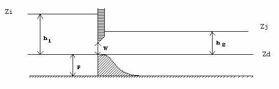
CEM88(D) : Weir / Orifice (low sill)
Weir - free flow
\(Q=\mu_f L \sqrt{2g} h_1^{3/2}\)
Weir - submerged flow
\(Q=k_F \mu_F L \sqrt{2g} h_1^{3/2}\)
\(k_F\) flow reduction coefficient in submerged flow. The flow reduction coefficient is a function of \(\frac{h_2}{h_1}\) and the value \({\alpha}\) of this ratio when switching from submerged flow to free flow. Flooding is achieved when \(\frac{h_2}{h_1} > \alpha\). Variation law of \(k_F\) was ajusted to experimental results (\(\alpha= 0.75\)).
Let's put \(x = \sqrt{1-\frac{h_2}{h_1}}\):
- If \(x > 0.2 : k_F = 1 - \left(1 - \frac{x}{\sqrt{1-\alpha}}\right)^\beta\)
- If \(x \leq 0.2 : k_F = 5x \left(1 - \left(1 - \frac{0.2}{\sqrt{1-\alpha}} \right)^\beta \right)\)
With \(\beta = -2\alpha + 2.6\), an equivalent free flow coefficient is calculated as above.
Undershot gate - free flow
\(Q = L \sqrt{2g} \left(\mu h_1^{3/2} - \mu_1 (h_1 - W)^{3/2} \right)\)
Experimentally, the flow coefficient of a valve is found to increase with \(\frac{h_1}{W}\). A law of variation of\(\mu\) was adjusted, in the form of:
\(\mu = \mu_0 - \frac{0.08}{\frac{h_1}{W}}\) with : \(\mu_0 \simeq 0.4\)
so \(\mu_1 = \mu_0 - \frac{0.08}{\frac{h_1}{W}-1}\)
To ensure continuity with the free surface for \(\frac{h1}{W} = 1\), \(\mu_F = \mu_0 - 0.08\) then has to be \(\mu_F = 0.32\) for \(\mu_0 = 0.4\)
Undershot gate - submerged flow
Partially submerged flow
\(Q = L \sqrt{2g} \left[k_F \mu h_1^{3/2} - \mu_1 \left(h_1 - W \right)^{3/2} \right]\)
\(k_F\) being the same as for free surface.
The switching from submerged flow to free flow was adjusted to experimental results, we then have a law like:
\(\alpha = 1 - 0.14 \frac{h_2}{W}\)
\(0.4 \leq \alpha \leq0.75\)
In order to ensure continuity with free surface operation, the free surface sumbmerged-free switch must therefore be for \(\alpha = 0.75\) instead of \(2/3\) in the orifice weir formulation.
Totally submerged flow
\(Q = L \sqrt{2g} \left(k_F \mu h_1^{3/2} - k_{F1} \mu_1 \left(h_1 - W \right)^{3/2} \right)\)
Formulation of \(k_{F1}\) is the same as the one of \(k_{F}\) replacing \(h_2\) with \(h_2-W\) (and \(h_1\) with \(h_1-W\)) for the calculation of coefficient \(x\) and of \({\alpha}\) (and therefore of \(k_{F1}\)).
Switching to totally submerged occurs for:
\(h_2 > \alpha_1 h_1 + (1 - \alpha_1) W\)
with : \(\alpha_1 = 1 - 0.14 \frac{h_2 - W}{W}\)
\((\alpha_1 = \alpha (h_2-W))\)
Weir gate operation is represented by the above equations and Figure below. Regardless of the type of flow under load, an equivalent free flow coefficient is calculated corresponding to a conventional free flow gate design:
\(C_F = \frac{Q}{L\sqrt{2g} W \sqrt{h_1}}\)
The default master coefficient for the device is a coefficient of \(C_G\) usually close to \(0.6\). We then transform it into \(\mu_0 = \frac{2}{3} C_G\), which allows to calculate \(\mu\) and \(\mu_1\) of the equation of the free flow gate.
Note: it is possible to obtain \(C_F \neq C_G\), even under free flow conditions, as long as the discharge coefficient increases with the ratio \(\frac{h_1}{W}\).
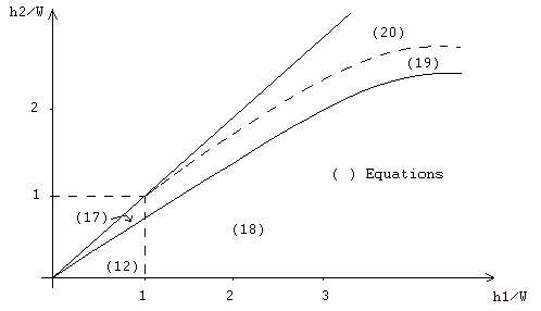
- (12) : Weir - free flow
- (19) : Orifice - partially submerged
- (17) : Weir - submerged
- (20) : Orifice - totally submerged
- (18) : Orifice - free flow
References
Baume, Jean-Pierre. 1988. « Modélisation des ouvrages de type : déversoir, vanne, orifice, dans les modèles d’hydraulique à surface libre ». Montpellier n°205-Document de travail 87.1. Montpellier, France: CEMAGREF. https://hal.inrae.fr/hal-04970129