Free flow sluice gate
Excerpt from Baume, J.-P., Belaud, G., Vion, P.-Y., 2013. Hydraulique pour le génie rural, Formations de Master, Mastère Spécialisé, Ingénieur agronome. UMR G-EAU, Irstea, SupAgro Montpellier.
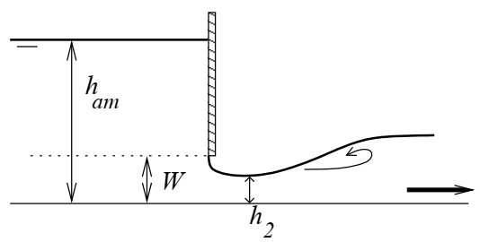
\(W\) is the gate opening, \(h_1\) the upstream water level and \(L\) the date width. The stage-discharge equation of the free flow sluice gate is derived from Bernoulli's load conservation relationship between the upstream side of the valve and the contracted section.
The height \(h_2\) corresponds to the contracted section and is equal to \(C_c W\) where \(C_c\) is the contraction coefficient. The stage-discharge equation is often expressed as a function of a flow coefficient \(C_{d}\) in the form of:
\(Q = C_d L W \sqrt{2g} \sqrt{h_1}\)
So we have the relationship between \(C_d\) and \(C_c\) :
\(C_d = \frac{C_c}{\sqrt{1 + C_c W / h_1}}\)
Numerous experiments were conducted to evaluate \(C_d\), which varies little around 0.6. As a first approximation, for a low \(W / h_1\) (undershot gate, most frequent case), \(C_d\) is close to \(C_c\) and can be chosen equal to 0.6.
Discharge coefficients \(C_d\) are given by abacuses, which can be found in specialized books if necessary. They range from 0.5 to 0.6 for a vertical sluice gate, from 0.6 to 0.7 for a radial gate, up to 0.8 for an inclined sluice gate.